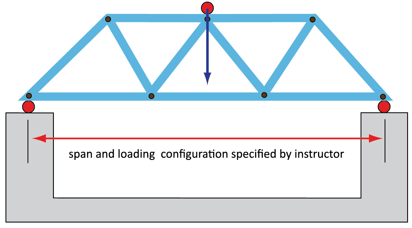
A metal truss or a set of parallel metal trusses is to be designed to achieve the highest load capacity to truss weight ratio as depicted below.
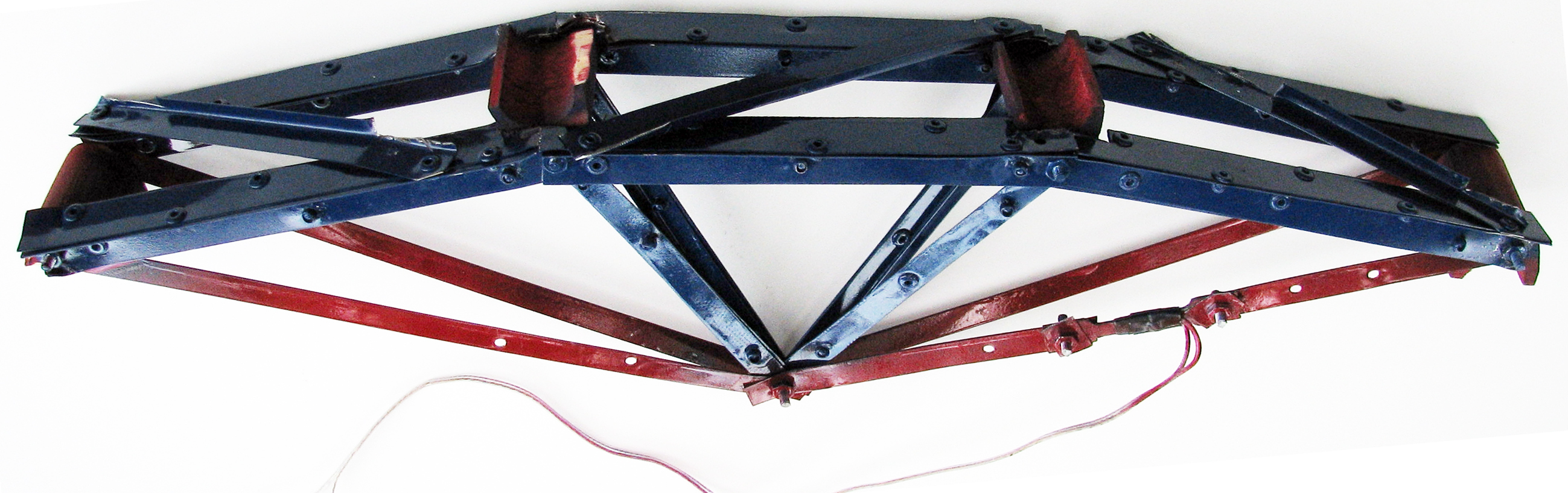
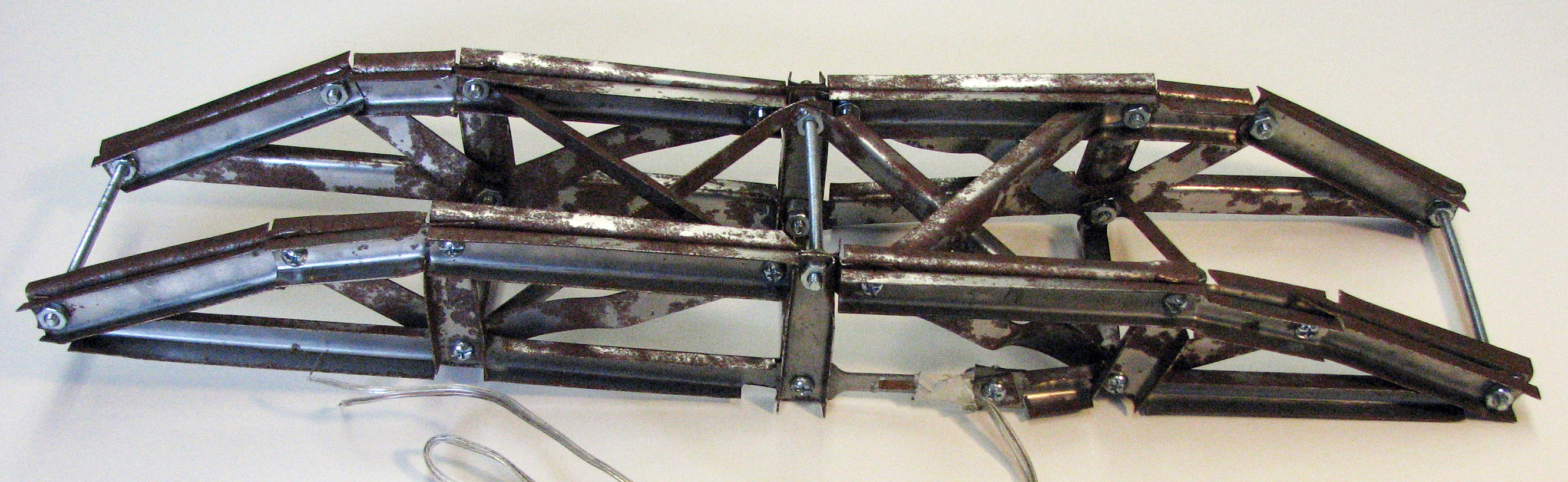
Loading will be applied at the supports and at one or more points as specified by the instructor (not necessarily at the center). Examples of trusses from previous quarters are provided here (1, 2, 3). Each group will be supplied with a piece of sheet metal from which the truss members will be cut.
The rules for the contest are listed below:
| 1. The maximum width of the truss or trusses will be 10 inches (the distance into the paper when referring to the diagram above); |
| 2. All external loads must be applied at the joints of the truss; |
| 3. Horizontal forces may not be reacted at the supports; |
| 4. The final design must be a truss that can be analyzed using the methods given in class (no beams are allowed, and the truss must be statically determinate); |
| 5. Only the metal provided by the College may be used to construct the truss; |
| 6. Members should be attached together at the joints using #8 machine screws coupled with washers and nuts whose diameters do not exceed 1/2 inch; |
| 7. No welding is allowed. |
| 8. You may paint your truss to enhance its appearance; |
| 9. Tension members should be clearly marked with a T, compression members with a C, and zero force members with a Z; |
| 10. All equipment needed to fabricate the truss is provided in Bogard Hall 304; |
| 11. The final weight of the truss (including fasteners, paint, . . .) may not exceed 120% of the weight of the provided materials; |
| 12. Rivets or other small fasteners may be used to make composite members. These fasteners may not be closer than 1 inch apart along the lengh of a member; |
| 13. A compliant material, such as a small piece of wood or rubber, may be placed on the truss at the point(s) of external loading to distribute the load to the truss more evenly. The weight of these blocks is considered to be part of the truss weight. This material must be local to the joint; |
| 14. No other types of fasteners such as bolts, tape, bondo, or wire is allowed. |
| 15. One of the tensile members must incorporate a load cell. |
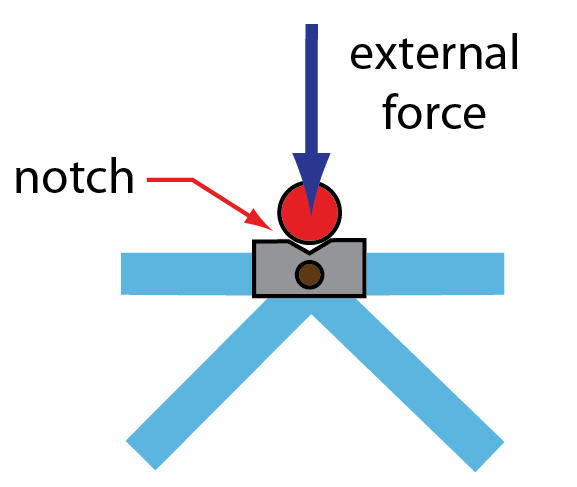
All contact between the truss and the loading fixture must occur at a joint. Contact between a member and the supports will likely lead to early failure. Be aware that your truss may slide off the loading mechanism; it may be helpful to make a loading notch at a support or at an external load as illustrated below. This is not usually a problem, but teams should be aware that their truss may move when loading is applied.
A sheet metal brake and shear, hand shears, a hole punch and a rivet gun will be provided for truss construction. The use of power tools is discouraged, as injury could occur. You must supply your own safety glasses and measuring devices when working in Bogard Hall, and you must be given permission and safety instructions before operating any equipment in the lab.
The grading will be based
on the design report, the design presentation, and on the performance of
the truss, as specified in the syllabus. Each group should supply the following in their report:
| 1. dimensioned sketch of their truss, with members in compression in blue, tension in red, and zero force members in yellow; |
| 2. calculations showing the stress in each member for an applied load of 1,000 lbs; |
| 3. a prediction of the mode (buckling or tensile failure) and the location of failure; and |
| 4. an estimate of the peak load that their truss will carry. |
The required format for the report is given HERE! The required joint labeling scheme is given HERE, and the required format for summarizing your truss calculations is given HERE.
Grading guidelines for the presentation are given HERE!