 (1)
(1)
LAB 4 - Centrifugal Pump Performance
Introduction
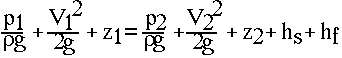
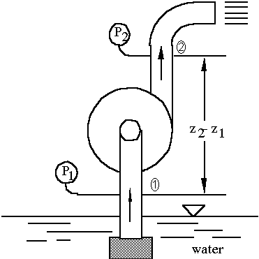
The head (hs) or total head or total dynamic head of a pump represents the net work done on a unit weight of fluid in passing from the inlet/suction flange to the discharge flange. Pump head is usually expressed in ft or m. The head can be determined by making an energy balance between a location on the suction side and another location on the delivery side as shown schematically in Figure 1. The energy equation between the suction side (section 1) and the discharge side (section 2), with the assumptions of no heat transfer and one dimensional flow at each section, can be expressed as
(1)
where: p = pressure
V = fluid velocity
g = acceleration due to gravity
z = datum head
hs = pump head
hf = frictional loss between 1 and 2
r = fluid density
With the pressure taps at the inlet and outlet flanges of the pump, hf is negligible. If the inlet and outlet pipe diameters are equal, V1 = V2, and the velocity head terms cancel out.
Flow Rate
The volume flow rate can be determined by one of two methods. The bucket and stopwatch method was previously described in Lab 3 - Minor Losses in Pipe Flow. A rotometer, scaled in liters/min, is also installed in the flow system and can be used for direct measurement of the flow rate.
Efficiency and Water Power
For calculating the pump efficiency, output power or water power (WP) should first be calculated from the total head hs and flow rate Q.
WP = Qrghs (2)
The hydraulic efficiency (hh) is equivalent to the fraction of the energy supplied to the pump impeller (shaft power) that ends up as usable water power. Shaft power (SP) can be expressed as
![]() (3)
(3)
where N = shaft speed (rpm)
T = shaft torque (N-m)
If the electrical input to the prime mover can be measured, the overall efficiency (ho) of an electric pump can be calculated. The overall efficiency is equivalent to the fraction of the input power that is actually delivered to the fluid (water power), where the input power can be determined from
Input Power = V I (4)
where I = motor current
V = supply voltage
Therefore,
![]() (5)
(5)
Similarity Analysis
From dimensional analysis, several dimensionless groups arise that are very important in the prediction of pump performance at a desired speed when the performance at a different speed is known.
 (6)
(6)
 (7)
(7)
 (8)
(8)
Eliminating D between p1 and p2, another dimensionless group p4 can be obtained
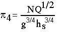 (9)
(9)
As g is almost constant, it may be removed from the group, and the resulting expression is called the specific speed of the pump.
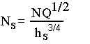 (10)
(10)
Note that the expression Ns has dimensions; therefore, it may be expressed in many units. One common practice in this country is to take Q in gpm, N in rpm and hs in ft. If SI units are used, Q should be in m3/s, hs in meters, and N in rpm, in which case the value of Ns for a centrifugal pump should lie between 10 and 150.
The specific speed of a pump may be defined as the speed at which a geometrically similar pump will deliver unit flow rate against unit head. Therefore, this parameter may often be used to predict the pump performance, particularly for large installations, based on smaller scale models of geometrically similar design. The specific speed also indicates the suitability of a pump to perform a particular task. Large discharge rates at a small head will produce a high specific speed, while small discharge rates at large heads will require a low specific speed.
Pump Laws
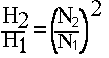
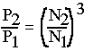
Because D, g and r are constants for a particular pump and liquid, these variables are taken out of p1, p2, and p3. The expressions that result include
 (11)
(11)
 (12)
(12)
 (13)
(13)
Knowing discharge (Q), head (H) and power (P) at one speed, these quantities can be calculated at another speed. The speed at which the performance is to be calculated should be within 25% of the speed at which experimental results are available.
Net Positive Suction Head (NPSH)
The rate at which a liquid will evaporate from its surface increases as the pressure is reduced, until at a certain level the evaporation develops within the fluid as bubbles of vapor. This condition is recognized as the process of boiling. Attempts to reduce the pressure further are prevented by the formation of even more vapor which maintains the original boiling pressure (i.e., the saturation pressure is directly related to the saturation temperature of the fluid).
The pressure of a fluid flowing in a system may be subjected to zones of localized low pressure, especially adjacent to a solid surface, such as a pump impeller. The resultant formation of vapor bubbles is termed cavitation. When the bubbles reach a zone of increased pressure, they collapse abruptly causing high impact pressures on the adjacent surface. This process can lead to damage of the surface in the form of pitting due to fatigue of the surface metal.
Cavitation also occurs at low pressures due to the release of bubbles of dissolved air. Air cavitation usually occurs at slightly higher pressures than vapor cavitation; however, both forms reduce the mass flow rate entering the pump and reduce the pump efficiency.
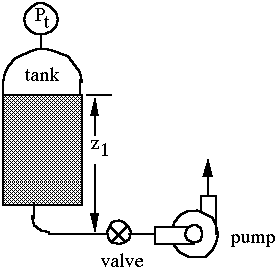
Net positive suction head is an indication of the suction characteristic of the pump and is a function of the vapor pressure, suction pressure, and velocity of the liquid in the suction pipe. It is an important parameter to find out whether a pump will cavitate or not under certain operating conditions. The available net positive suction head (NPSHA) can be determined by the following:
![]() (14)
(14)
where: Pv = vapor pressure of the water at pump
inlet
Pt
= tank pressure
hf
= frictional losses from the tank to the pump
The required net positive suction head is a parameter provided by the manufacturer as a function of pump speed and discharge. For optimal pump performance, the available NPSH should always be greater than the required NPSH. Figure 2 gives further description of the variables used in the above definition.
Apparatus
The Cussons Hydraulic Bench consists of a steel frame carrying equipment upon two platforms and an instrument panel. At the lower level is the water reservoir and circulating pump; at the upper level, the frame forms a cradle for the drainage tray/working surface. A bucket for measuring water flow is suspended below the drainage tray. The instrument panel includes a pressure gage and pump control valve. The hydraulic bench is shown schematically in Figure 3.
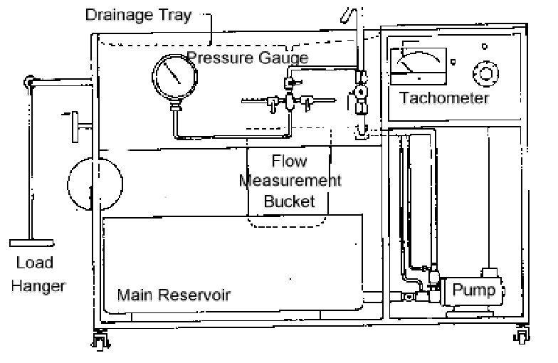
Figure 3. Cussons P6112 Hydraulics Bench Fitted with Variable Speed
Unit
Water is drawn from the main reservoir by the centrifugal pump and delivered via a plastic flexible hose to the control valve mounted on the front panel. From this point the water is delivered to the test panel using another section of flexible hose. After use, the water is discharged into the drainage tray, passing into the bucket of the measuring apparatus which is carried on a beam. The free end of the beam is designed for use with a hanger carrying masses of a known value. Flow rates can be measured by timing the accumulation of water in the bucket with a stop watch. The measurement bucket is emptied using a drain plug at its base. When measurement of the water flow rate is complete, the water is emptied back into the main reservoir.
The pump is a high speed centrifugal type. The motor normally operates at 5000 rpm with a maximum flow rate of 45 liters/min. The maximum head produced is 14 m. A controller is connected to the motor which allows the speed to vary between 0 and 5000 rpm. Speed is indicated by means of an analog tachometer.
Objectives
Pump Head and Overall Efficiency
1. Ensure the main valves on the pump inlet and outlet are wide open.
2. Close the main control valve and turn on the pump. Set the speed control to near maximum and open the control valve on the front panel to its full open position.
3. Observe the flow rate using either the rotometer or the bucket/stopwatch method. Record the motor current and voltage; the pump speed; the inlet and outlet pressures. These last two may not be observed simultaneously since they both use the same gage. Ensure that only one tap on the manifold is open at a time.
4. By means of the control valve, reduce the flow rate in about 8 even increments down to zero. Adjust the speed controller so that the pump speed remains constant as the flow rate changes. Record the same data as in step 3.
5. Close the control valve and switch off the pump.
6. Calculate the pump head and overall efficiency at each flow rate. Plot a combined graph of pump head and efficiency against the independent variable (Q). Find the maximum efficiency and maximum pump head together with their corresponding discharge rates.
7. Repeat the above procedure for a second pump speed, which should be within 25% of the original speed. There may be a slight change in the pump speed due to the varying load. Keep the speed constant by adjusting the speed controller. This portion of the pump experiment must also be conducted at constant speed.
8. Using the pump laws, calculate Q and hs at the second speed based upon the data from the first pump speed. Plot and compare the predicted pump performance with the experimental results at the second speed. Note that the application of the pump laws may be achieved with the two pump speeds reversed in this analysis.
Cavitation
1. Record the water temperature and barometric pressure. Determine the pipe inside diameter on the suction side of the pump (3/4" schedule 40 - 0.824 in inside diameter)
2. Switch on the pump and fully open the control valve.
2. Set the pump speed to its maximum value.
3. Slowly close the main valve on the pump inlet. Observe closely the effect on the water in the plastic tube connected to the inlet. Record a description of any changes that are observed and the corresponding pressure at the pump inlet, the height of the free surface in the tank above the inlet pipe, and the mass flow rate.
4. Switch off the pump and allow the apparatus to drain back to the main reservoir.
5. Calculate NPSHA at the point at which cavitation begins. Compare the temperature and pressure at which cavitation occurs with the saturation temperature and pressure values given in the steam tables.
References
1. Hodge, B.K., Analysis and Design of Thermal Systems, 2nd ed., Prentice-Hall, Englewood Cliffs, New Jersey, 1990.
2. White, F.M., Fluid Mechanics, 2nd Ed., McGraw-Hill Book Co., New York, 1986.
3. Holman, J.P., Experimental Methods for Engineers, 4th Ed., McGraw-Hill Book Co., New York, 1984.
4. G. Cussons Ltd., "Cussons Losses in Pipe Bends and Fittings - Apparatus Type P6125," Technical Manual 2/80/6125, Manchester, England, 1980.