ME
354 - Thermofluids Laboratory
Spring 1997
LAB 7 - Convection Heat Transfer from a Flat Plate
Introduction
One of the fundamental problems of interest in convection heat transfer
considers flow over a heated flat plate. While the geometry could not be
any more basic, parallel flow over a flat plate, as shown in Figure 1,
occurs in a number of engineering applications. In addition, this geometry
may be a good first approximation for flow over surfaces that are slightly
contoured, such as airfoils or turbine blades. In this type of external
flow, the boundary layers develop freely, without any constraints imposed
by adjacent surfaces. Consequently, there will always be a region of the
flow outside the boundary layer in which velocity and temperature gradients
are negligible.
 Figure 1. Parallel Flow Over a Flat Plate
By nondimensionalizing the boundary layer conservation equations, it can
be shown that the local and average convection coefficients may be correlated
by equations of the form
Nux = f1(x*, Rex,
Pr) (1)
 (2)
(2)
where Nux = Nusselt number (hx/kf)
Rex = Reynolds number (ux/ )
)
Pr = Prandtl number
x* = dimensionless axial location (x/L)
h = heat transfer coefficient
kf = thermal conductivity of the fluid
u = free stream velocity
 = kinematic
viscosity
Note that the properties of the fluid are based on the film temperature
and that the subscript x has been appended to the Nusselt number to emphasize
that the interest here is in local conditions on the surface. The overbar
indicates an average value of the Nusselt number from x* = 0 to the point
of interest. One of the primary objectives of convection heat transfer
is to find the functions f1 and f2.
Either theoretical or experimental approaches could be used for this purpose.
Two boundary conditions that are frequently used in heat transfer analysis
are 1) uniform surface temperature and 2) uniform surface heat flux. For
a uniform heat flux boundary condition on a flat plate exposed to forced
convection flow, integral methods [1] may be used to determine the local
Nusselt number for laminar flow. The correlation that results is
 (3)
(3)
In a similar fashion, it can be shown that for turbulent flow
 (4)
(4)
When compared to the results for a uniform surface temperature, these solutions
give values of Nux that are 36 and 4% larger for laminar
and turbulent flow, respectively.
It is quite common to have a situation where the leading edge of the flat
plate is unheated, otherwise known as an unheated starting length. In this
case, the surface temperature of the unheated section equals that of the
fluid (Ts = T_). As shown in
Figure 2, the velocity boundary layer begins to develop at the leading
edge (x = 0), while the thermal boundary layer development starts at x
=  . An
integral boundary layer solution can be used [1] to develop an expression
for the local Nusselt number that accounts for the unheated length. The
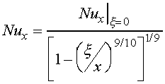
equation for laminar flow is
 (5)
(5)
where  is given by Equation 3. Similarly, the unheated starting length affect
on heat transfer from a flat plate experiencing turbulent flow can be expressed
as
 (6)
(6)
where  is given by Equation 4. The equations for the unheated starting length
apply for x >
  only.
According to Incropera and DeWitt (1990), in order to obtain average Nusselt
numbers for
  < x < L, these equations would have to be integrated numerically.
 Figure 2. Flat Plate in Parallel Flow with an Unheated Starting Length
Objectives
The primary objective of this exercise is to measure the local heat transfer
coefficient and Nusselt number for a heated flat plate experiencing forced
convection cooling. The plate has a short unheated starting length. The
measured data is to be compared to theoretical predictions.
Experimental Apparatus
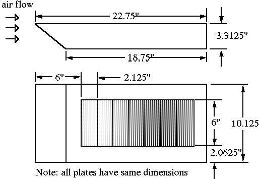
The flat plate for this experiment consists of a smooth rectangular surface,
22 3/4 inches long by 10 1/8 inches wide. Seven rectangular flat plates
are installed side-by-side at a location 6 inches from the leading edge.
The metal plates are heated from beneath by individual strip heaters. Temperatures
of the plates may be monitored by a digital thermometer connected to 2
type-T thermocouples installed in each of the seven sections between the
heaters and the metal plates. The strip heaters have been wired in parallel
and power is supplied to the heaters through a DC power supply. The total
power to the heaters may be determined from measurements of the total voltage
supplied to the heaters and the total current to the heaters determined
from the voltage drop across a 10 mW shunt.
The power supplied to each heater is simply the total power divided by
7 (number of individual heaters). The underside of the flat surface is
insulated with approximately 2 inches of foam board insulation. A dimensioned
drawing of the flat plate apparatus is shown in Figure 3.
 Figure 3. Heated Flat Plate
The AEROLAB Educational Tunnel supplies the forced air for the experiment.
The flat plate apparatus has been installed such that the flat surface
is centered within the 12 inch square test section. A variable speed motor
drives the wind tunnel centrifugal fan, allowing different free stream
velocities to be tested. The free stream air speed within the wind tunnel
is displayed on the wind tunnel control panel in mph.
Newton's Law of Cooling may be used to calculate the local heat transfer
coefficient and Nusselt number. This equation may be written as
 (7)
(7)
where qw is the heat flux per unit area.
Experimental Procedure
-
Determine the local barometric pressure and temperature.
-
Turn on the power to the strip heaters. The lab instructor will specify
where the power supply should be set.
-
Turn on the power to the wind tunnel and adjust the motor speed control
in order to obtain the desired flow rate. The lab instructor will once
again suggest an appropriate flow rate. Allow the flow to attain a steady
state condition.
-
Monitor and record the free steam temperature and velocity and the
plate temperatures over time. Continue until a steady state condition is
achieved. Data acquisition is accomplished with a Keithley Series 500 Data
Acquisition and Control system. Most of the important data can be read
from the computer monitor and may also be printed when desired.
-
At steady state, record the following: all plate temperatures, total
voltage to the heaters, voltage drop across the shunt (or the current supplied
to the heaters), air speed, and air temperature.
Data Reduction and Points of Interest
Calculate the wind tunnel Reynolds number. Determine the heat supplied
to each plate. Find local values of hx, Rex,
and Nux. Compare the experimentally determined parameters
with the theoretical predictions. A graphical representation of the results
is desirable.
-
Consider the heat loss from the plate due to radiation to the surroundings
and by conduction through the underside of the flat plate apparatus. Make
estimates of these losses and discuss means of minimizing or accounting
for them. Do these losses help to explain any discrepancies that are observed
between the experimental and theoretical data?
-
Is the uniform heat flux boundary condition a good approximation in
this case?
-
How does the experimental data agree with the external flow assumption
that the hydrodynamic and thermal boundary layers develop freely? Does
the presence of the wind tunnel walls affect the boundary layer development
along the flat plate?
-
Discuss how the heat transfer coefficient varies for flow over a flat
plate through the laminar, transition , and turbulent flow regimes. Based
on your results, did transition from a laminar to a turbulent boundary
layer occur for your test? If so, determine the distance from the leading
edge where the experimental flow became turbulent. Compare to the theoretical
value and discuss any discrepancies.
-
Consider the effect that the heated plate apparatus has on the air
flow in the wind tunnel. Discuss modifications to the apparatus to minimize
these effects or ways in which these effects may be assessed.
References
-
Kays, W.M., and Crawford, M.E., Convective Heat and Mass Transfer,
McGraw-Hill, New York, 1980.
-
Incropera, F.P. and DeWitt, D.P., Fundamentals of Heat and Mass Transfer,
3rd ed., John Wiley & Sons, New York, 1990.
-
Holman, J.P., Heat Transfer, 7th Ed., McGraw-Hill Book Co., New York,
1990.
-
White, F.M., Fluid Mechanics, 2nd Ed., McGraw-Hill Book Co., New York,
1986.
-
Chappa, S.C. and Canale, R.P., Numerical Methods for Engineers, 2nd
Ed., McGraw-Hill, New York, 1988.


 (5)
(5)
 (6)
(6)


 (7)
(7)