 (1)
(1)
LAB 6 - Drag on Various Three-Dimensional Bodies
Introduction
Boundary-layer theory is quite interesting and helps give one a sense of the qualitative behavior of viscous flow over fully immersed bodies; however, because of flow separation, the theory usually does not produce good quantitative data of the complete flow field. At present, there is no complete theory that is capable of predicting the forces acting on an arbitrary shape immersed in a flowing fluid at an arbitrary Reynolds number. Thus, experimentation is required in most cases to obtain the data of interest for external flows.
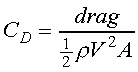
The net force due to pressure differences acting on the surface of a body fully immersed in a flowing fluid is called pressure drag or form drag. Form drag combined with skin friction drag gives the total drag exerted on the immersed body. The total drag exerted on an immersed three-dimensional body is to be studied in this experiment. Drag is typically presented in the form of the drag coefficient, defined as
(1)
where the characteristic area A may differ depending on the body
shape and the term 1/2![]() V2
is the dynamic pressure. The area A is usually one of three types:
1) Frontal area, the body as seen from the stream; this area is suitable
for spheres, cylinders, cars, projectiles, and other thick, stubby bodies,
2) Planform area, the body seen from above; suitable for wings and hydrofoils
or other wide, flat bodies, and 3) Wetted area, typically used for surface
ships. The area to be used in the calculation of
CD
in this experiment is the frontal area. Further information regarding the
concepts to be studied are given in Section 7.6 in White (1994).
V2
is the dynamic pressure. The area A is usually one of three types:
1) Frontal area, the body as seen from the stream; this area is suitable
for spheres, cylinders, cars, projectiles, and other thick, stubby bodies,
2) Planform area, the body seen from above; suitable for wings and hydrofoils
or other wide, flat bodies, and 3) Wetted area, typically used for surface
ships. The area to be used in the calculation of
CD
in this experiment is the frontal area. Further information regarding the
concepts to be studied are given in Section 7.6 in White (1994).
Experimental Apparatus
The AEROLAB Educational Tunnel is of the Eiffel or Open Circuit type with a 12" by 12" test section. The airspeed is infinitely variable from 0 to 145 mph (do not exceed 120 mph for this experiment!) with a 10-hp drive operated by a variable frequency system. The tunnel achieves a high energy ratio through its large contraction ratio of 9.5:1, its small-angle diffuser, and efficient fan system. The high energy ratio in not important (at this level) in saving electrical costs but it is important in indicating low aerodynamic losses which are associated with intermittency and unsteadyness. The fan operates in an acoustically treated section to reduce the noise level. The control/instrumentation panel indicates all of the raw data including airspeed and axial force. Fig. 1 shows the control/instrumentation panel with the units of the indicated data inserted into each digital display box.

Figure 1 Control/Instrumentation Panel for the AEROLAB Wind Tunnel
Objectives
1. Determine the drag coefficient for your assigned body at Reynolds numbers corresponding to test section velocities ranging from 50 to 120 mph at 5 mph increments (Try to obtain at least 10 data points). Start at the highest possible speed (not to exceed 120 mph) when collecting the data. Data for a 4 inch diameter sphere is also provided at the end of this handout.
2. Compare the value of CD for your assigned body and for the sphere to values given in the literature (your fluid mechanics textbook).
3. Plot the CD data as a function of Re along with calculated uncertainty bars for your assigned body and the sphere data.
Procedure
1. Obtain the local barometric pressure and room temperature.
2. The instructor or TA will give you a model to be tested. Measure the diameter of the model with calipers.
3. Install the model in the wind tunnel using the appropriate mount. There are two types of model mounts. The Teaching Assistant will indicate which should be used for your model.
BE VERY CAREFUL NOT TO USE EXCESSIVE FORCE WHEN INSTALLING THE MODEL. THE SMALL STRAIN GAGES USED FOR FORCE MEASUREMENT CAN BE DAMAGED EASILY.
4. Flip the power switch to ON at least 30 minutes before use.
5. Zero the Axial Force digital output using the knob beneath the digital display.
6. Zero the Air Speed (mph) digital indicator using the knob beneath the display. Note: the Airspeed indicator will always indicate -0.01 mph for all settings below 0.00. The Air Speed indicator should be set by reducing the indicated value from a positive Air Speed down to the desired value of 0.00.
7. Check that the fan controller knob is turned all the way counterclockwise to the full off position.
8. Turn on the fan motor switch.
9. Turn the fan controller knob slowly clockwise to increase the air speed to the desired value. Start collecting data at the highest speed obtainable (not to exceed 120 mph) for your object.
10. Record the air speed (mph) and drag (lbf). Set the air speed to the next desired value and repeat. Try to obtain at least 10 data points.
11. When the test is completed, turn the air speed knob counterclockwise to an indicated 0.00 mph. Then turn off the fan switch.
Questions
1. Compare your test results to other published data and discuss the similarities and differences. Discuss the significance of the uncertainty data as it is related to the comparison of your calculated data and that given in White (1994). Do your results agree with the published data? If not, why?
2. In the case of the sphere data compare the test data with Fig. 7.16b in White (1994).
3. Discuss the indicated trends in the data and relate these to the physics of the flow over the immersed body. For the sphere data and your test model, does drag coefficient versus Reynolds number indicate a change in the flow field? Provide a physical explanation for your answer. Was transition from laminar to turbulent flow obtained?
Sphere Test Data
Sphere Diameter = 4 inches
P(atmosphere) = 706.4 mm Hg
T(ambient) = 72oF
Uncertainty in Drag = +/- 0.03 lbf
Uncertainty in Velocity = +/- 0.4 mph
|
|
|
|
|
|
|
|
|
|
|
|
|
|
|
|
|
|
|
|
|
|
|
|
|
|
|
|
|
|
|
|
|
|
|
|
|
|
|
|
|
|
|
|
|
|
|
|
|
|
|
|
|
|
References
1. White, F.M., Fluid Mechanics, 3rd Ed., McGraw-Hill Book Co., New York, 1994.
2. Janna, W.S., Introduction to Fluid Mechanics, 3rd Ed., PWS Publishing, Boston, 1993.