![]()
![]()
![]()
![]()
![]()
![]()
![]()
![]()
Window Layout
Below is a screenshot of the Watson Assembly Lab. As you will note, the major sections of the lab are numbered and explained below the image.
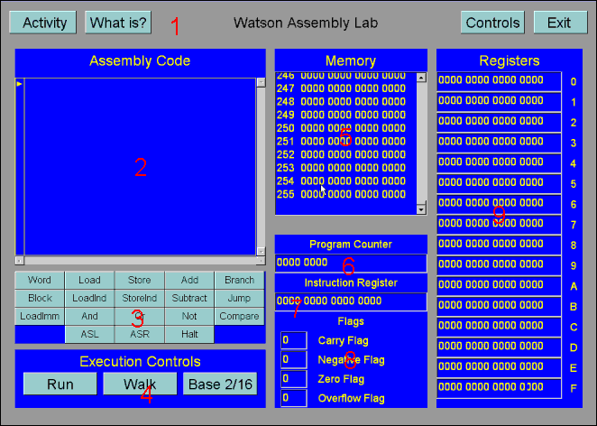
1. Watson Control Bar - The common Watson control bar for all applications. This bar contains all the functions to run an activity and get important information about the lab.
2. Code Window - This window holds your actual program, and lets you edit the code held there.
3. Instruction Buttons - These are the buttons your click on to insert code into the Code Window.
4. Execution Buttons -
- Run - Executes the program sequentially until it finishes.
- Walk - Steps through your program one line at a time allowing to study exactly what happens in the memory and registers after each instruction.
- Base 2/16 - Switches the memory and register views between base 2 (BIN) and base 16 (HEX).
5. Memory Window - This window shows the contents of the 256 (0-255) memory locations. All values are initially 0. You can view these numbers in Base 16 (HEX) by pressing the Base 2/16 button under the Execution Controls.
6. Program Counter - This register contains the value of the Program Counter (PC). This register shows what statement in the program is currently being executed.
7. Instruction Register - This register contains the value of the current instruction being executed. The first four bits is the machine instruction being executed and the last twelve bits are the parameters for that instruction.
This table shows the breakdown of the command "ADD REGF, REGD, REGE"
|
8. Flags - This part of the window shows the four machine flags.
- Carry Flag - This flag gets set high whenever the result of an operation, such as ADD, carries a 1.
- Negative Flag - This flag gets set high whenever the result of an operation is negative.
- Zero Flag - This flag gets set high whenever the result of an operation is zero.
- Overflow Flag - This flag gets set high whenever an overflow occurs. An overflow will occur whenever the value that is to be stored is outside the range of permissible values for that space in memory.
9. Registers - This window shows the contents of the 16 internal CPU registers.