Editing Circuits
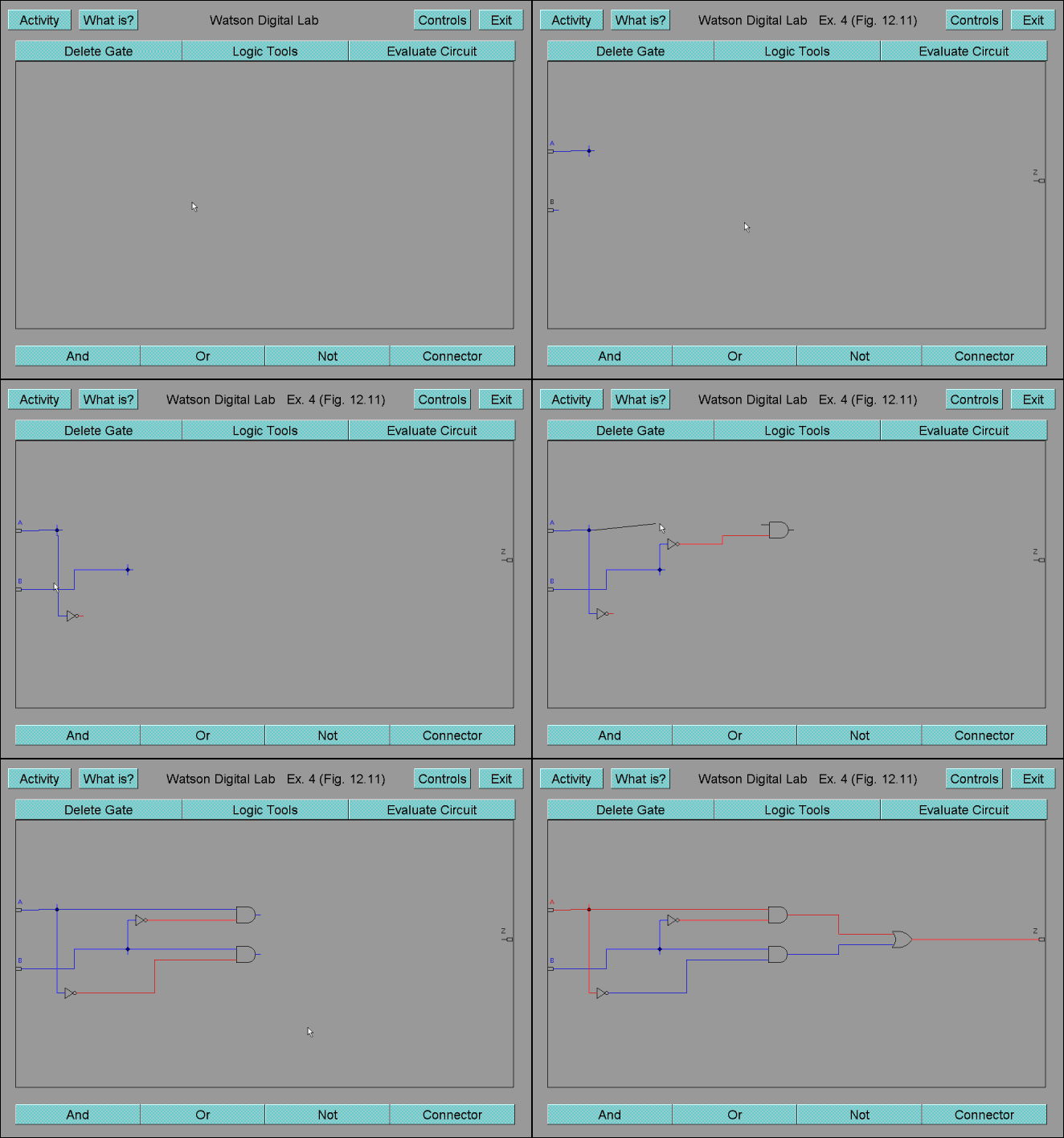
To begin constructing a circuit, add one or more gates to the drawing area by clicking the button corresponding to the gate that you want and then click in the drawing area in the place that you want the gate. Then you are ready to draw the wires connecting the gates. To draw wires between two gates, click on either the output pin of the first gate or the input pin of the second gate and drag a wire (line) to the input/output pin of the other gate. Once the wire is touching the pin, you can release the wire and it should connect. If not, try again. (It often takes a little practice before you get used to connecting the gates in this fashion.) You will notice that once you connect all input pins of a gate to an input gate (either through other gates or directly), the output pin(s) of the gate will turn the appropriate color (blue or red). This provides you a way for you to check your circuit as you create it to make sure it is functioning properly.
If you place a gate in the drawing area and then later realize that you need to move the gate, click in the middle of the gate, drag the gate to where you want it, and release the gate. As you do this, you will notice that all wires are redrawn to accommodate for the gate's move. This allows you to move gates in a circuit without having to redraw the wires connected to that gate.
The input gates change the logic value of the entire circuit. Clicking inside of an input gate will change the logic value of that pin, and essentially the entire circuit. The wires and pins are color coded to aid in determining the logic value of the pins. A red wire or pin has a 1 on it while a blue wire or pin has a 0 on it. All input gates start out blue.
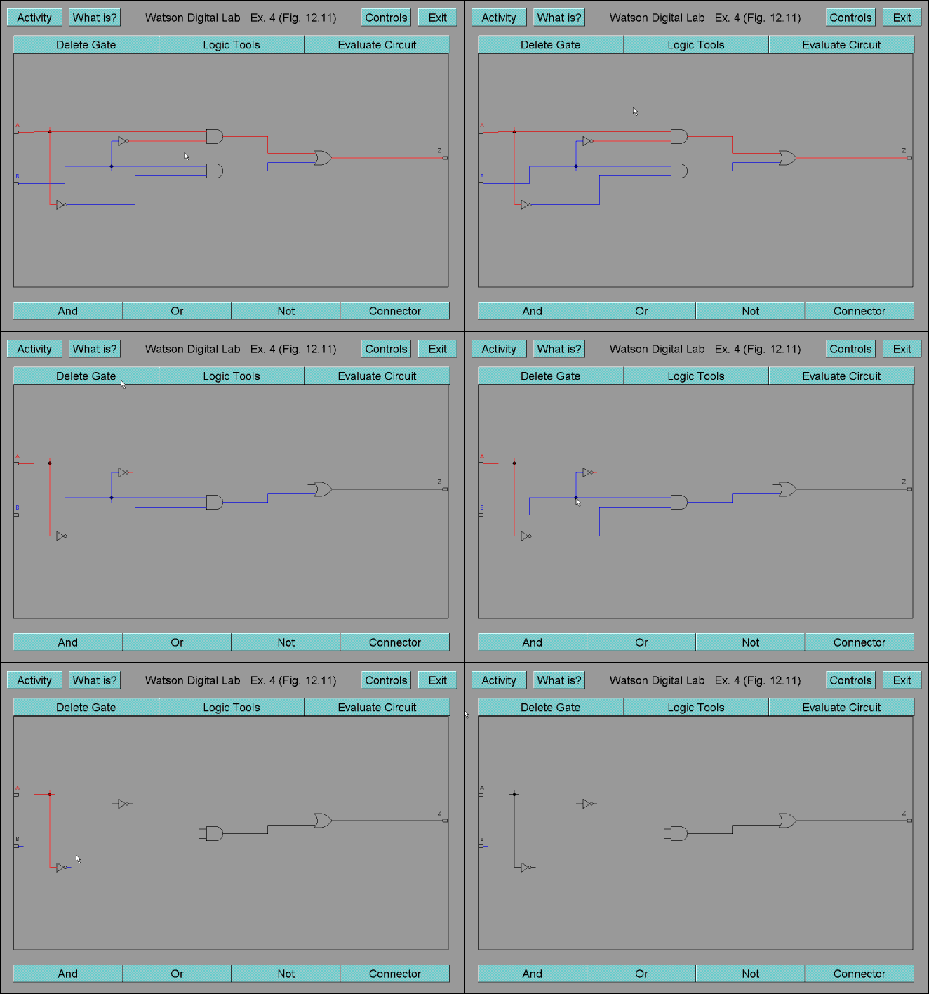
Below is an example of creating an exclusive or (XOR) circuit. After the circuit is completed, notice that changing the value (color) of one of the input pins changes the value (color) of all of the wires and pins in the circuit.

Below you will find an illustration of how to delete a gate and a wire. To delete any gate (except an input or output), click the 'Delete Gate' button and then click the gate you wish to delete. To delete a wire, redraw at least part of the wire and then release the mouse button.
