Window Layout
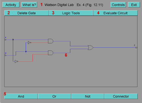
Below is a screenshot of the Watson Digital Lab. As you see, the major sections
of the lab are numbered and explained below the image.

- Watson Control Bar - The common Watson control bar for all applications. This bar contains all the functions to select an activity and get important information about the lab.
- Delete Gate Button - Aids the user in editing the circuit by allowing the user to delete a specified gate.
- Logic Tools Button - Provides various logic tools to help the user
determine problems in the circuit or to assist as a learning tool. Currently,
only the Boolean Probe and Truth Table are implemented.
- Boolean Probe - Provides the Boolean equation of any selected gate
in the circuit. A * symbolizes an and operation, a + symbolizes an
or operation, and a / symbolizes a not operation. To use this
tool, click this option in the choice selector and press OK. Then click the
gate (input, output, and, or, not, or connector)
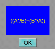
you wish to know the Boolean equation of. Below is an example of the Boolean
Probe for the output of an Exclusive Or.

- Truth Table - Displays the truth table corresponding to the circuit displayed in the Drawing Area. To use this tool, click this option in the choice selector and press OK. The truth table will then be calculated and displayed.
- Boolean Probe - Provides the Boolean equation of any selected gate
in the circuit. A * symbolizes an and operation, a + symbolizes an
or operation, and a / symbolizes a not operation. To use this
tool, click this option in the choice selector and press OK. Then click the
gate (input, output, and, or, not, or connector)
you wish to know the Boolean equation of. Below is an example of the Boolean
Probe for the output of an Exclusive Or.
- Evaluate Circuit - Checks the circuit to see if it is correct and notifies the user. This option is not available for the Scratchpad activity.
- Gate Buttons - Allows the user to
add the specified gate
to the drawing area.
- And - An and gate takes in two inputs and gives one output.
Only if both inputs are 1 does the gate output a 1. Otherwise it outputs a 0.

- Or - An or gate takes in two inputs and gives one output.
If at least one input is 1, the gate outputs a 1. Otherwise it outputs a 0.

- Not - A not gate takes in one input and gives one output.
This gate outputs a 1 if a 0 is inputted and outputs a 0 if a 1 is inputted.

- Connector - A connector gate takes in one input and gives
three outputs. This gate just outputs the same value that is input, but it outputs
three separate copies of this value. This allows one input to be connected to
more than one gate.

- And - An and gate takes in two inputs and gives one output.
Only if both inputs are 1 does the gate output a 1. Otherwise it outputs a 0.
- Drawing Area - Area where the circuit will be constructed and edited. Holds the input gates and output gates, which cannot be deleted or created by the user. Each activity has its own pre-defined set of input and output gates.